555 Timer Schematic - Introduction to Breadboarding | The Paleotechnologist / They consist of t1, d1, d2, d3, d4, c1, and c2.. They consist of t1, d1, d2, d3, d4, c1, and c2. In 2017, it was said over a billion 555 timers are pr. Here's our schematic in its current shape. 555 timer helpers schematic adding of a resistor and capacitor to the trigger will not work for very short trigger or output pulses because there is a rc delay in the decay and recovery of the voltage at the trigger. This tutorial provides sample circuits to set up a 555 timer in monostable, astable, and bistable modes as well as an in depth discussion of how the 555 timer works and how to choose components to use with it.
Working and schematic diagram of clap swith circuit These components are the unregulated supply section. So the time period after which this circuit will automatically turn on/off the output is fixed and can be found out by using the formula mentioned in the calculation section. It was commercialized in 1972 by signetics. May 23, 2021 · schematic diagram of dual dc regulator 15v using transistor and zener diode.
Pin on electronic from i.pinimg.com Working and schematic diagram of clap swith circuit Nov 16, 2016 · monostable multivibrator using 555 timer may 22, 2017 3 to 5 led chaser circuits using arduino, with control potentiometer december 24, 2016 blink 2 led flasher using arduino november 6, 2016 The below figure is the schematic of a simple automatic on off timer with a fixed timing resistor and capacitor. May 23, 2021 · schematic diagram of dual dc regulator 15v using transistor and zener diode. This article covers every basic aspect of 555 timer ic. The 555 timer ic is an integrated circuit (chip) used in a variety of timer, delay, pulse generation, and oscillator applications. 555 timer is a digital monolithic integrated circuit (ic) which may be used as a clock generator. It is similar to the previous circuit.
They consist of t1, d1, d2, d3, d4, c1, and c2.
We're working on a simple led flasher that includes a 555 timer and some basic components. In other words, 555 timer is a circuit which may be connected as a stable or monostable multivibrator. 555 timer ic (16) 8051. Here's our schematic in its current shape. This article covers every basic aspect of 555 timer ic. It is similar to the previous circuit. These components are the unregulated supply section. In this article, we cover the following information about 555 timer ic. So the time period after which this circuit will automatically turn on/off the output is fixed and can be found out by using the formula mentioned in the calculation section. 555 timer is a digital monolithic integrated circuit (ic) which may be used as a clock generator. 555 timer helpers schematic adding of a resistor and capacitor to the trigger will not work for very short trigger or output pulses because there is a rc delay in the decay and recovery of the voltage at the trigger. Nov 16, 2016 · monostable multivibrator using 555 timer may 22, 2017 3 to 5 led chaser circuits using arduino, with control potentiometer december 24, 2016 blink 2 led flasher using arduino november 6, 2016 In 2017, it was said over a billion 555 timers are pr.
They consist of t1, d1, d2, d3, d4, c1, and c2. With those details out of the way, let's jump into your schematic and get started! It was commercialized in 1972 by signetics. The 555 timer is a chip that can be us… It is similar to the previous circuit.
555 Timer Circuit Schematic | Electronics projects, Timer ... from i.pinimg.com They consist of t1, d1, d2, d3, d4, c1, and c2. Working and schematic diagram of clap swith circuit These components are the unregulated supply section. 555 timer is a digital monolithic integrated circuit (ic) which may be used as a clock generator. This article covers every basic aspect of 555 timer ic. It is similar to the previous circuit. Here's our schematic in its current shape. 555 timer helpers schematic adding of a resistor and capacitor to the trigger will not work for very short trigger or output pulses because there is a rc delay in the decay and recovery of the voltage at the trigger.
Working and schematic diagram of clap swith circuit
Derivatives provide two (556) or four (558) timing circuits in one package. These components are the unregulated supply section. It is similar to the previous circuit. In 2017, it was said over a billion 555 timers are pr. 555 timer is a digital monolithic integrated circuit (ic) which may be used as a clock generator. 555 timer ic (16) 8051. With those details out of the way, let's jump into your schematic and get started! The 555 timer ic is an integrated circuit (chip) used in a variety of timer, delay, pulse generation, and oscillator applications. Working and schematic diagram of clap swith circuit Here's our schematic in its current shape. This tutorial provides sample circuits to set up a 555 timer in monostable, astable, and bistable modes as well as an in depth discussion of how the 555 timer works and how to choose components to use with it. 555 timer helpers schematic adding of a resistor and capacitor to the trigger will not work for very short trigger or output pulses because there is a rc delay in the decay and recovery of the voltage at the trigger. In other words, 555 timer is a circuit which may be connected as a stable or monostable multivibrator.
It was commercialized in 1972 by signetics. We're working on a simple led flasher that includes a 555 timer and some basic components. Derivatives provide two (556) or four (558) timing circuits in one package. So the time period after which this circuit will automatically turn on/off the output is fixed and can be found out by using the formula mentioned in the calculation section. The below figure is the schematic of a simple automatic on off timer with a fixed timing resistor and capacitor.
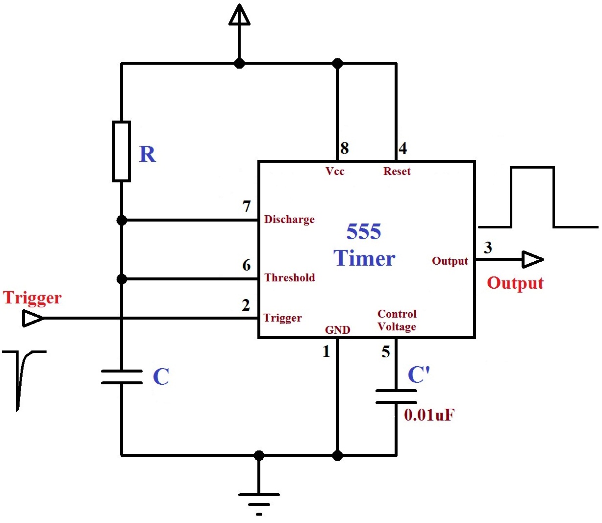
Monstable Multivibrator using 555 Timer from electrosome.com In this article, we cover the following information about 555 timer ic. Working and schematic diagram of clap swith circuit In other words, 555 timer is a circuit which may be connected as a stable or monostable multivibrator. This article covers every basic aspect of 555 timer ic. Here's our schematic in its current shape. In more simple words, 555 timer is a monolithic timing circuit, which can produce accurate timing pulses with 50% or 100% duty cycle. Nov 16, 2016 · monostable multivibrator using 555 timer may 22, 2017 3 to 5 led chaser circuits using arduino, with control potentiometer december 24, 2016 blink 2 led flasher using arduino november 6, 2016 It is similar to the previous circuit.
With those details out of the way, let's jump into your schematic and get started!
This article covers every basic aspect of 555 timer ic. 555 timer helpers schematic adding of a resistor and capacitor to the trigger will not work for very short trigger or output pulses because there is a rc delay in the decay and recovery of the voltage at the trigger. Derivatives provide two (556) or four (558) timing circuits in one package. It is similar to the previous circuit. In 2017, it was said over a billion 555 timers are pr. The 555 timer is a chip that can be us… It was commercialized in 1972 by signetics. The below figure is the schematic of a simple automatic on off timer with a fixed timing resistor and capacitor. You may already know that se/ne 555 is a timer ic introduced by signetics corporation in 1970's. In other words, 555 timer is a circuit which may be connected as a stable or monostable multivibrator. May 23, 2021 · schematic diagram of dual dc regulator 15v using transistor and zener diode. 555 timer ic (16) 8051. We're working on a simple led flasher that includes a 555 timer and some basic components.


0 Komentar